

|
[145] The Viking Landers have two eyes and therefore can view the landscape in three dimensions, just as we do with our own eyes. However, presentation of stereoscopic pairs has been a frustrating problem. Because the camera separation is almost 1 m, objects close to the spacecraft are viewed with orientation equivalent to that for an object at the tip of one's nose. The pictures have to be carefully rectified so that the relative scales remain the same throughout the scene. The distance between the images must be controlled to permit optimum fusion.
Some persons can appreciate the stereoscopic effect much more easily than others. There is, however, one fairly reliable guide to the viewer's success. If, as he peers through the stereoscope, you ask him if he sees the third dimension and he responds noncommittally "yes," then you know he has not. Wait a few minutes and you will hear an exclamation of surprise and wonder. Then you will know he has seen it. The effect is so unusual, literally drawing you into the scene, that very few people come upon it without excitement.
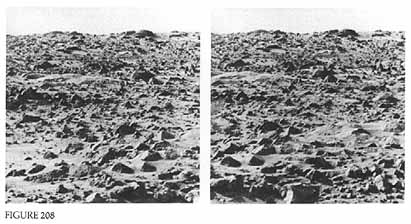
On the following pages we present 19 stereopairs. To look at them use the viewer enclosed in the envelope inside the back cover. Most persons find it easiest to focus their attention on some prominent object in the farfield, preferably on the horizon. Position the centerline of the viewer equidistant between the two images of the object. Looking through the viewer, fuse the two images into a single image. To assure yourself of a fused image rotate or translate the viewer slightly. You will see the two images separate and then fuse as the viewer is returned to proper orientation.
For some persons, fusion will not be accompanied immediately by a threedimensional effect. If you are uncertain regarding your own success, continue to look at the landscape, moving the viewer slightly if necessary. When the third dimension is optimally perceived, a succession of ridges and depressions will be so sharply delineated as to give the impression of a series of discrete vertical planes, moving away from the spacecraft. When you have obtained the appropriate effect for the farfield, work your way back into the nearfield. Once you "lock in," subsequent attempts will be considerably easier. Perhaps the most striking phenomenon to be observed stereoscopically is the undulating character of the scene, particularly at the Viking 1 site. Figures 208 to 215 comprise a panorama in front of the spacecraft, moving in a clockwise direction. Figures 216 and 217 reveal details of rocks in the foreground. Figures 218 and 219 show topography in the vicinity of the sediment drifts. Figures 220 to 223 comprise a second panorama looking to the right of the Lander toward the northwest. Drifts of sediment, intermixed with dusters of boulders, occur throughout the scene.
Three stereopairs, figures 224 to 226, have superposed on them contour lines generated with the aid of a computer. In one case (fig. 226) the lines are drawn to represent horizontal planes intersecting with the surface, similar to a conventional topographic map. In the other two images (figs. 224 and 225) the planes are vertical so that vertical profiles are superposed. During the mission, this combination of graphic and pictorial data proved a valuable aid in planning movement of the surface sampler arm.
The last two figures, 225 and 226, are views of the Lander 2 site. Although there is some relief in the scene, the topographic variations are not as dramatic as at the Viking 1 site.
This is an appropriate place to end our discussion of Mars. So vivid is this three dimensional effect that, as you look at these ridges and depressions, you may get the impression you can actually step from your chair and onto the surface of Mars. Someday our descendants will.


